© AC
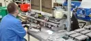
© AC 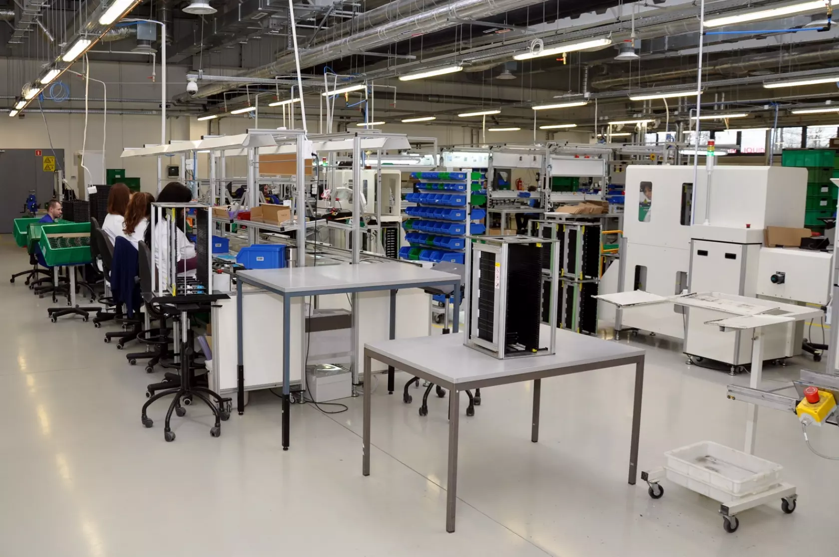 One of the stages of manufacturing LPG controllers is assembling threaded components
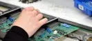
 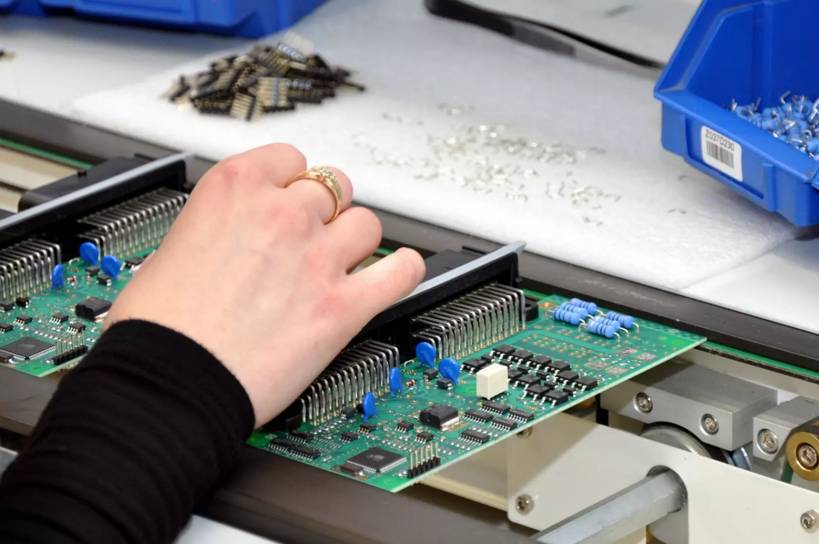 Assembling threaded components is carried out manually
 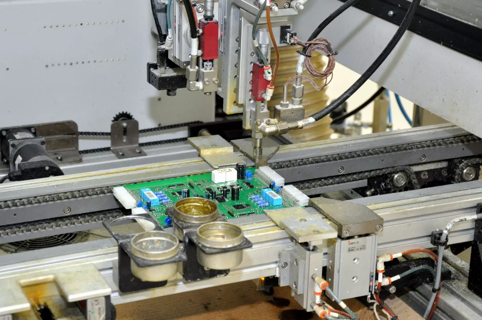 Lacquering PCBs protects them against difficult weather conditions
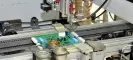
 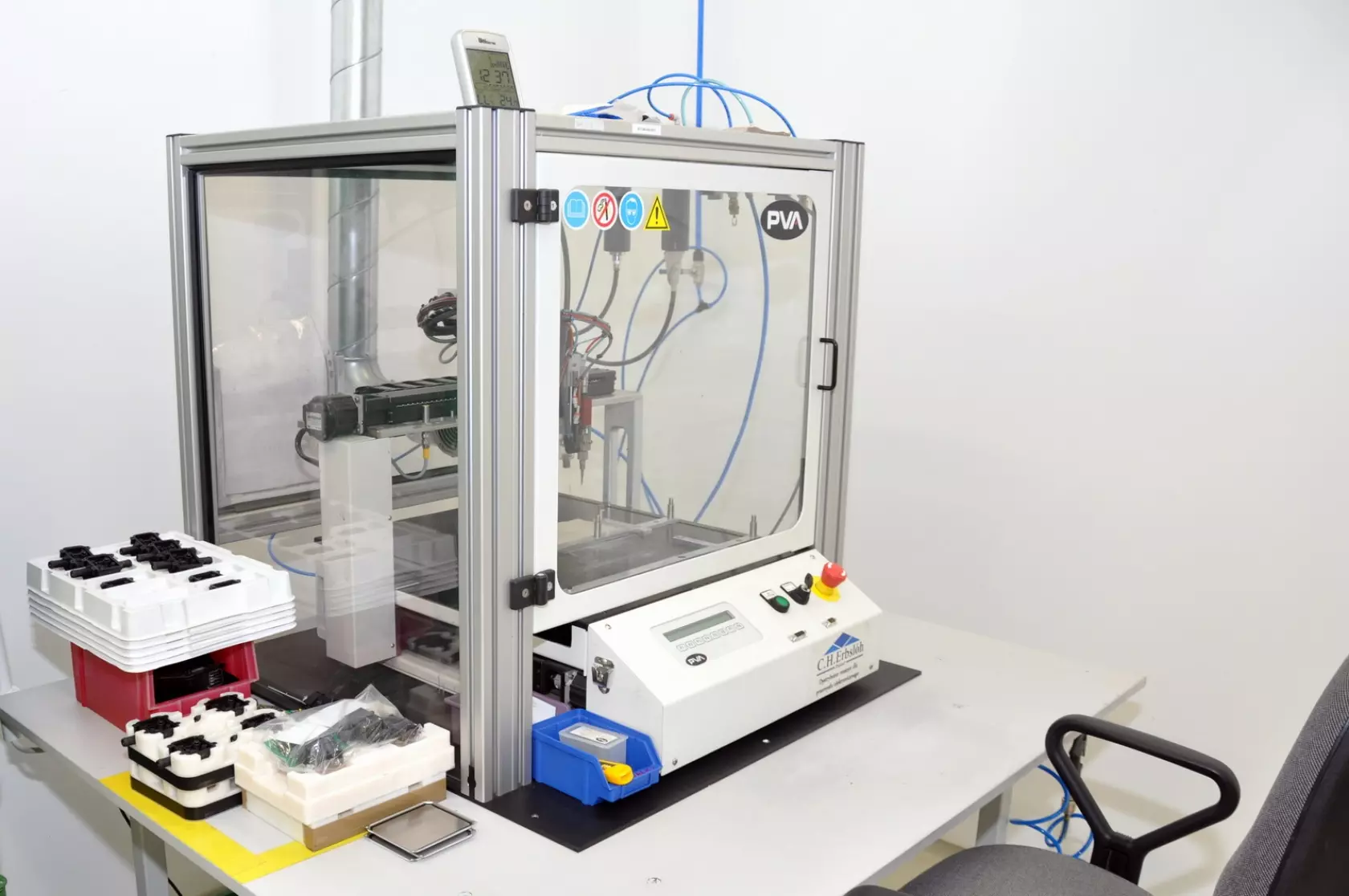 A device that pours silicone seals
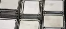
 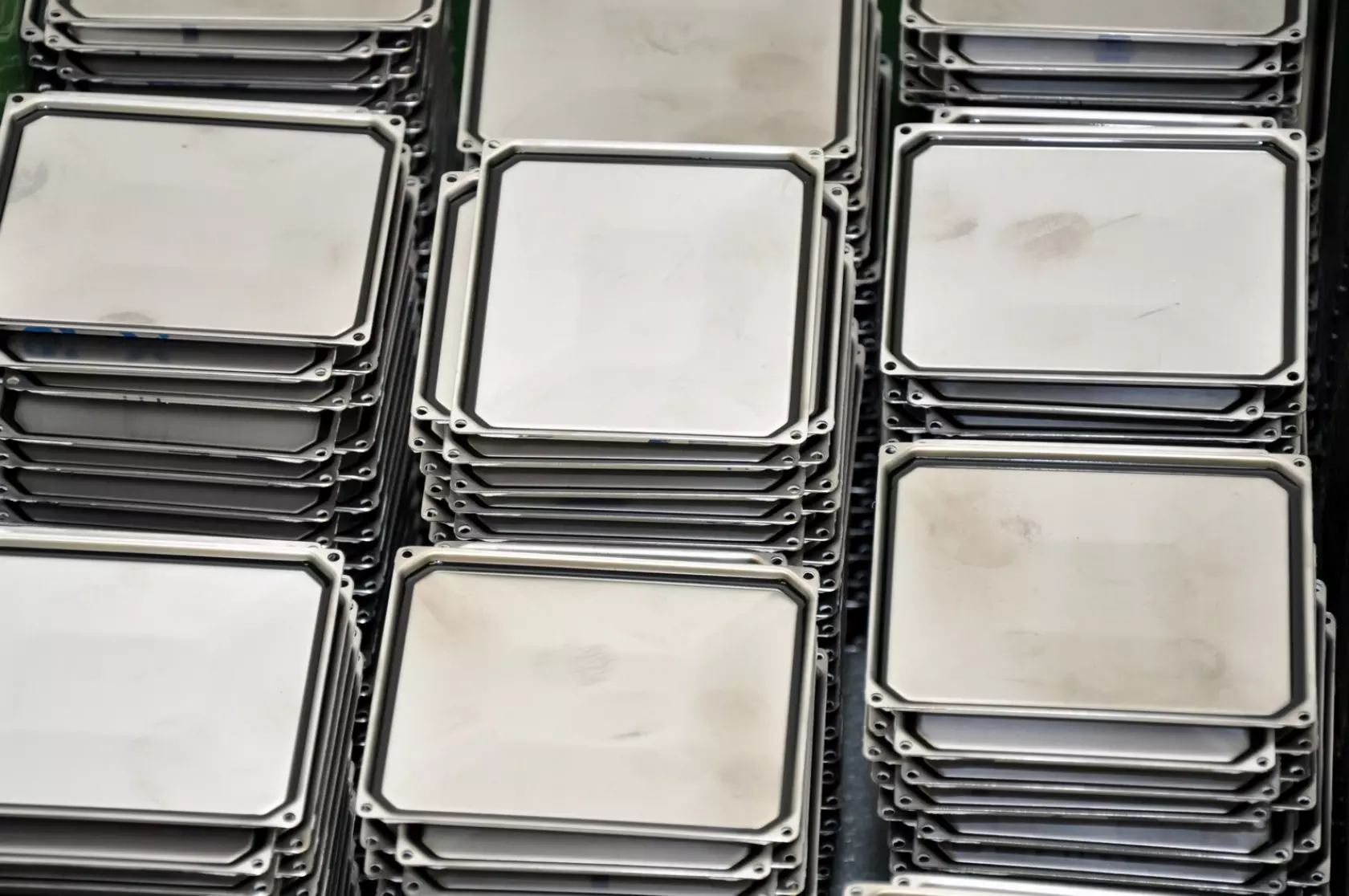 Covers for controllers housing with a silicone seal
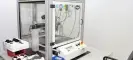
 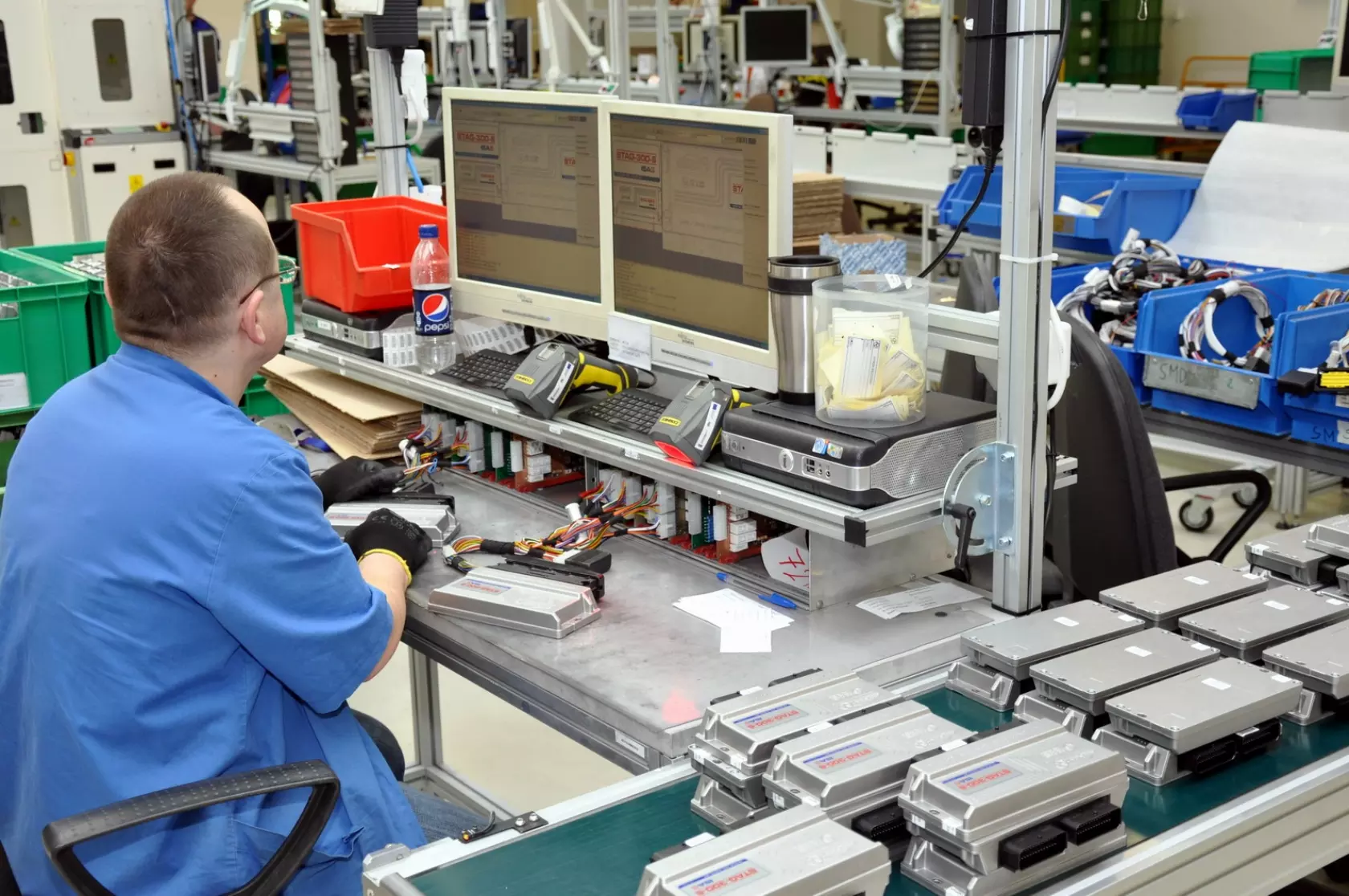 Final check of LPG controllers before they’re packed
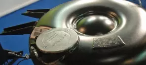
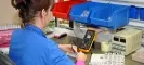
 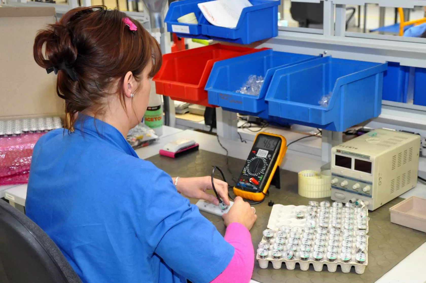 Calibration of LPG level sensors
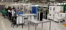
 © ACNew manufacturing space was created between AC SA’s Research and Development Center and previously existing production halls
The controllers were previously produced in other rooms at the same plant, while the production of wire harnesses was moved from a plant located in different part of Białystok.
Change of location significantly improved the production process, helping to maximize the potential of the machine park. It was also a chance to introduce a number of modifications which shortened operation time or reduced consumption of materials and, as a result, production costs.
New areas were properly prepared for all the production processes that will be carried out inside these particular rooms which is especially important in the production of controllers.
Humidity of 40 to 60% and room temperature of about 23° C provide the right conditions for the special processes necessary during the production of controllers, mainly soldering electronic components on the boards. Proper conditions in the hall guarantee the stability of this process because materials used for soldering keep proper physico-chemical parameters. It ensures repeatability of this process.
 © gazeo.comSMD assembly department has two identical production lines that can apply 96 thousand surface mounted electronic components during an eight hour shift
The SMD department
Printed-circuit boards delivered by the suppliers – 4- or even 6-layered in the newest controllers (conductive tracks are also placed within the laminate) – are subjected to the first process that prepares them for the later stages of production.
The first thing to do – a very important one, carried out before production processes – is to mark every board with a special 2D code (laser branded). It allows to identify the board at every stage of controller’s production, as well as later – e.g. during warranty service. This code in the company’s database records the entire history of each controller (production date, elements used in its construction including information about their manufacturers, info on the production line operator and many other important information), including parameters of the processes carried out during production of each controller (soldering, varnishing of boards).
After applying the code, the boards are dusted. This removes the residue left after branding so that the code is clearly visibly.
Marked with a 2D code (data matrix), the boards – or actually whole packages of boards – reach the production line along with their electronic components. First stages in the production involve preparing the boards to be embedded with electronic components.
Each of the controllers includes SMD (Surface Mounted Devices) as well as typical threaded elements. The process of mounting the first type of elements is fully automated and is carried out on two production lines.
 © gazeo.comThe heart of one of production lines in SMD assembly department – a device that applies surface mounted electronic components onto a board
Elements designed for surface mounting (SMD) get to the production line in special holders. The variety of electronic components is limited at the stage of designing devices. This reduces the inventory diversity. Additionally, the company benefits from reducing the number of changeovers of production line when there’s a change of production.
Each holder with electronic components has a bar code, therefore in the process of stacking the elements on the board, the code of the material PCB (Printed Circuit Board) and the code of the holder are linked. This eliminates the possibility of errors as, by analyzing the codes, the machine is able to control whether proper electronic components were supplied.
The first stage of manufacturing controllers’ PCBs involves screen printer which – through an appropriate template (different for each product’s PCB) – applies the adhesive used for mounting SMDs.
PCBs with the adhesive are transferred to the heart of the production line, which is a machine that arranges SMD’s electronic components. This complex device is equipped with a precisely controlled head, which takes elements from the line using negative pressure (they are sucked by the head) and places them on the PCB. A photo of the elements is taken moments later. This way the machine evaluates whether the element was appropriately placed and adjusts its position if needed.
The use of several PCBs joined together means that each operation is carried out on several boards simultaneously, which speeds up the production significantly. In addition, handling of larger boards is easier in devices with automatic shift. The aim is to separate the boards as late in the production cycle as possible.
After applying all elements, a laminate sheet moves into a furnace in which the adhesive is cured. This way one side of PCB is assembled (ready for wave soldering). It’s the bottom side. PCBs are designed so that lighter elements (fixed by gluing) are placed on the bottom side.
Then, on the second line, the top side of the board is assembled. This side contains soldered components. The early stage looks similar as in the case of gluing, but instead of the adhesive, soldering paste is applied in the screen printer (by special template).
Soldering takes place in a furnace where the entire board is heated. The paste becomes fluid and connections are soldered. The whole process is carried out in such way that the elements assembled with the paste on the underside do not fall off. They are held by the surface tension of the solder.
 © gazeo.comAssembling a connector – the biggest threaded component in an LPG controller’s board
Both lines are identical so each can be used for gluing or soldering (as needed). They are operated directly by two people. A third employee takes care of production planning and logistics (ordering components or watching the sequence of orders).
Each of the two lines is able to apply 48 thousand SMDs per hour, which means that 1,500 PCBs can be manufactured by each shift (SMD production department operates in two shifts). Each line can be doubled which is not done but potentially can double the manufacturing capacity.
Assembling threaded elements
Automating threaded elements assembly, although possible, is very expansive due to the need for complex technology and specialized machine park. At AC SA, threaded electronic elements are assembled manually.
Along with the production order, threaded elements are issued, such as connectors, relays, resistors and capacitors. The elements are delivered on the lines so they have to be prepared for PCB mounting earlier (suitable cutting and shaping leads so that they fit into the holes in the board).
The connector is one of the first threaded elements mounted. It’s the main and surely the biggest threaded element. Pre-assembly of the connector involves placing it in respective PCB holes and fixing it so that it doesn’t move. The connector must also be properly positioned so that it doesn’t cause stress after mounting the board in the housing. It’s also convenient to use it to carry PCB to further production stages.
Threaded elements are also branded with appropriate codes that allow the identification of individual components mounted in a finished controller (its history can be traced back).
After installing all threaded elements, PCB or laminate sheet (depending on the product) goes to the soldering unit. Prior to this process, some elements need to be covered, e.g. to protect the connectors from having contact with hot solder. Any contact with molten metal is only possible in some specific places (where soldering is required).
 © gazeo.comA unit for wave soldering is filled with inert nitrogen which improves the quality of joints and reduces melting loss
Threaded elements are soldered on the wave which means that in the soldering unit (in its crucible filled with molten solder) on the surface of molten metal a wave is produced which has contact with pins of soldered elements, and solders joints are created.
Soldering unit consists of three zones. The first one is responsible for fluxing – applying flux to the bottom side of the board. Its task is to remove oxides from soldered joints and to improve wettability with solder. Flux also reduces surface tension of solder so that solder meniscus have appropriate shape (no cold solder joints).
The second zone includes soaking which activates flux (it requires a temperature of about 130° C). Oxides are then removed from surfaces where solder joints are to be created so that solder has higher adhesion (it sticks better).
Zobacz stronę producenta:
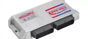
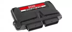
STAG
 loading results...